Cajal, M., Lawson, K.A., Hill, B., Moreau, A., Rao, J., Ross, A., Collignon, J. and Camus, A. Development, 139, 423-426 (2012) doi: 10.1242/dev.075499
Clonal and molecular analysis of the prospective anterior neural boundary in the mouse embryo.
Sample Preparation
A 5 to 6 somite stage embryo that had been cultured for 24 hours from the LSEB stage was fixed and the ectoplacental cone and chorion removed in washing buffer.
Protocol
Fixation
Embryos were fixed in 2.5% Glutaraldehyde in 0.1M Cacodylate Buffer pH 7.3 + 0.1M Sucrose. 2Hrs for 24 hours.
Wash
Embryos were washed in 0.1M Cacodylate Buffer + 0.1M Sucrose for 2x10 mins. Embryos for storage were kept in this solution at 4°C.
Dehydration
Increasing concentrations of ethanol in distilled water were used to dehydrate the embryos. 10%,30%,50%,70%90% ethanol each for 2x30mins before a final 3 changes of 100% dry ethanol.
Infiltration
Due to the very fragile nature of these young embryos, Propylene Oxide was omitted as a transition fluid for the epoxy resin. Instead mixtures of TAAB PREMIX (medium grade) plus accelerator in 'dry' ethanol (1:2, 1:1 and 2:1 for 2 hrs each) were used to assist the infiltration.
All embryos were then transferred into a thin layer of complete resin overnight at room temperature to infiltrate.
At the same time a thin layer of resin plus accelerator was poured onto the bottom of the final embedding moulds (flat aluminium foil dishes) and polymerised overnight at 60°C to give the bottom layer of the 'sandwich' technique used for embedding.
Embedding
After the infiltration stage was complete the embryos were transferred to fresh resin plus accelerator that had been added to the foil dishes as another thin layer. The embryos were allowed to sink to the interface of the two layers, carefully orientated with a fine glass rod, then placed in a 60°C oven for 3 days to polymerise.
OPT (Optical Projection Tomography)
Prior to sectioning, the trimmed block was imaged by OPT (Optical Projection Tomography) in Zeiss Immersion Oil (518N) using the autofluorescence of the embryo.
Sectioning
The embryos were then subject to histology sectioningThe embryo for sectioning was cut out with a small hacksaw, trimmed with a single edge razor blade and clamped in a vice type ultratome chuck. The chuck was fixed to the ultratome and the block face trimmed with a glass knife until it was almost at the embryo.
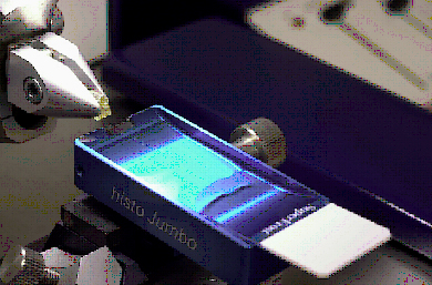
The glass knife was then replaced with a diamond knife with an 'in-house' plastic scoop/trough attached. Serial 1μM frontal sections through the head and 2μM sections of the rest of the embryo were cut onto distilled water in the trough. Contact adhesive was used on the top and bottom edge of the block to allow ribbons of sections to be cut. Ribbons of sections were transferred to a pool of distilled water on a cleaned glass slide (2-3 per slide). The slide was placed on a hot plate at 70°C and the sections allowed to stretch out fully for 2 mins. The ribbons of sections were orientated on the slide and the water withdrawn with a fine tipped pastette.
The slide was dried vertically overnight at room temperature then heated on a hot plate at 70°C for 1 hr to adhere the sections to the slide prior to staining.
Floating out

Staining
The slides were stained with 1% Toluidine Blue in 1% Borax in distilled water diluted 1:20 in a coplin jar in a water bath at 60°C for 30 seconds. The slides were then rinsed in distilled water and allowed to air dry before mounting them in microscope oil with a coverslip.
Image Capture
Configuration DImage Processing
The model embryo was reconstructed from the digital section-images (579 x 1 μm sections of the head, 374 x 2 μm sections of the rest of the embryo) using a three-stage process comprising primary pair-wise registration, shape optimisation and finally quality check and shape-controlled re- alignment. The first stage was applied to the whole embryo, the second and third stages to the head only, making the latter an independent reconstruction. In all of these stages individual images are aligned using rigid-body transformation i.e. no shear or non-linear warping of an individual 2D image.
Primary Registration
The section images were registered in a pair-wise sweep through the stack, i.e. the second image aligned to the first, then the third image to the second and so on. For each alignment the global mutual information was maximised by adjusting the rigid body transform (translation and rotation only). This was implemented using the Mattes Mutual information [Mattes et al, 2003] as implemented by the ITK toolkit [www.itk.org, Ibanez et al, 2005]. This primary registration was subject to an automatic quality check by calculating the sum of squared grey-value differences for each adjacent image pair. Potential anomalies will result in a sudden jump in this measure and can then be checked and if needed re-aligned after adjusting search space parameters. This technique provides a fully automatic registration but can suffer from a gradual drift in alignment and correct reconstruction of the original geometry is not guaranteed. This is corrected in the shape optimisation phase.
Shape Optimisation
In this phase a 3D optical projection tomography (OPT) image of the embryo before physical sectioning is used in conjunction with biological knowledge to adjust the automatic alignment so that the resulting geometry is more faithful to the original embryo. For this application biological knowledge is used to define the mid-sagittal plane and this was coupled with the OPT image to ensure correct symmetry. The process was applied as three steps:
- 1. Nuclei of 45 selected cells in the base of the neural groove were used
as markers of the rostrocaudal axial midline of the embryo, and their
coordinates obtained in the original section plane. A spline was
defined by these coordinates and the midsagittal plane was defined as
the best fitting plane through this spline using least squares
distance of the spline from the plane. Each image position was then
adjusted so that the intersection point of each image plane with the
spline were brought to the mid-sagittal plane using only translation
and rotation;
- 2. A shear correction was imposed at a small angle to the midline, with
the correction plane cutting the midline at the level of the junction
of neural groove, foregut and oral plate, to rectify differences with
the OPT dimensions viewed dorsally;
- 3. A second shear correction was made orthogonal to the first to adjust
discrepancies in the lateral view.
All these adjustment were made using the Woolz image processing tools.
Quality Check and Shape Controlled Re-Alignment
Local misalignments, detected either on the surface rendering of the reconstruction or as breaks in cellular continuity in the yz orientation, were adjusted by reapplying the mutual-information maximisation within a neighbourhood of the error (typically +/-10 planes). To ensure that the global shape remained correct, the first and last section image of the neighbourhood are kept fixed. This realignment used a combination of the ITK mutual-information alignment option coupled with Woolz tools to interpolate the rigid-body transforms.
Ibanez L., Schroeder W., Ng L. and Cates J., The ITK Software Guide Second Edition Updated for ITK version 2.4, 2005 (Kitware Inc) ISBN: 1-930934-15- 7.D. Mattes, D. R. Haynor, H. Vesselle, T. K. Lewellen, and W. Eubank. PET-CT image registration in the chest using free-form deformations, 2003, IEEE Trans. on Medical Imaging, 22(1): 120 - 128.


